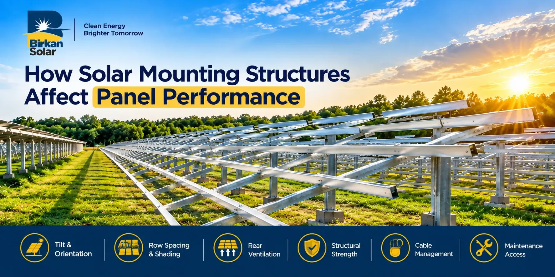
A solar mounting structure affects how much sunlight modules receive, how hot they operate, how well they resist wind and movement, and whether technicians can inspect and clean them safely. It does not generate electricity, but poor geometry, shade, flexing, corrosion or inaccessible rows can reduce output and shorten reliable service.
Good design balances energy yield with roof or ground constraints, wind loads, drainage, waterproofing, material compatibility, cable management and maintenance. The optimum is therefore not always the steepest tilt or the maximum number of modules that physically fit. It is the layout that delivers dependable lifetime energy without compromising the host structure.
Birkan Solar describes on-grid, rooftop and industrial solutions along with solar mounting structures. Review its on-grid solar panel structure, rooftop solar system and industrial solar solutions when comparing layouts for different sites.
Performance pathways at a glance
| Structure decision | Performance effect | Risk if poorly handled |
|---|---|---|
| Tilt and azimuth | Changes annual and seasonal irradiance | Lower yield or unwanted generation profile |
| Row spacing | Controls inter-row shade and land/roof use | Mismatch and morning/evening losses |
| Rear clearance | Influences module temperature and access | Hotter modules and difficult maintenance |
| Strength and stiffness | Maintains geometry under wind and load | Movement, damage or electrical faults |
| Material and coating | Determines long-term durability | Corrosion and loosening |
| Cable/access layout | Supports reliable operation and service | Abrasion, water traps and unsafe work |
Tilt changes annual and seasonal energy
Tilt determines the angle at which direct sunlight reaches the module and affects how diffuse light, reflected light and soiling behave. The best fixed tilt depends on latitude, horizon, weather, desired seasonal output and available space. A lower tilt can fit more modules in a constrained area but may increase dirt retention and reduce winter exposure.
Use energy modelling with local weather data rather than a latitude-only rule. Compare annual kWh, monthly profile and clipping for realistic inverter sizing. If the client values daytime self-consumption more than maximum annual yield, orientation and tilt may be optimized around the load profile and export rules.
Orientation aligns production with the sun and the load
In the northern hemisphere, south-facing fixed arrays commonly maximize annual irradiation when unshaded, but east-west layouts can broaden the production curve and use roof area differently. Roof geometry, parapets, equipment and structural zones may restrict the feasible azimuth.
Do not rotate rows only to increase module count. Model the alternative layouts with the same assumptions, including temperature, shading, mismatch and inverter limits. The selected orientation should state why it supports the owner’s energy objective.
Row spacing controls shade and density
One row can shade the next when the sun is low. The effect depends on row height, tilt, spacing, sun angle and terrain. Shaded cells can limit current in a string until bypass diodes act, so a small geometric shadow may cause a disproportionate electrical loss depending on module and string layout.
Select a design sun angle or use time-series simulation, then test energy lost against the value of extra modules. Leave sufficient access for inspection and cleaning. On a rooftop, walkways and fire or emergency routes may be required even when tighter packing appears to improve nameplate capacity.
Rear ventilation influences module temperature
Photovoltaic module power generally falls as cell temperature rises above the reference condition. Mounting clearance allows convective airflow behind modules and can reduce operating temperature compared with a tightly enclosed surface. The benefit varies with wind, roof temperature, module construction and array geometry.
Clearance must also satisfy structural, waterproofing and wind considerations. A high stand-off may improve airflow but increase wind forces and visual exposure. Model or specify the complete arrangement rather than treating ventilation as an isolated dimension.
Structural stiffness protects alignment and components
Rails, purlins, posts and connections must carry dead load, wind pressure and suction, maintenance load, snow where applicable and any seismic or site-specific effects. Excessive deflection can alter alignment, stress module frames, loosen connections or damage cables. Dynamic wind response and edge-zone suction deserve attention on exposed roofs.
The structural engineer should verify the module’s permitted clamp zones, support spacing, rail span, fastener forces, foundation or roof anchorage and host-building capacity. Generic component ratings are not a project calculation. For existing buildings, assess the roof and its corrosion or deterioration before adding the array.
Mounting method affects roof integrity
Penetrating systems transfer loads to structural members but require durable waterproofing. Ballasted systems avoid some penetrations but add dead load and must resist sliding, uplift and overturning. Standing-seam clamps can be effective when seam strength and clamp compatibility are verified. Each method has different load paths.
Coordinate with the roof manufacturer and warranty terms. Do not fasten only into thin sheeting unless the engineered detail permits it. Route water freely to drains and avoid supports that trap debris. Roof access, fall protection and future membrane or sheet replacement should be planned at design stage.
Alignment limits mechanical and electrical mismatch
Consistent rail height keeps modules coplanar and reduces twisting. Survey roof or ground tolerances before fabrication. Use adjustable details only within their certified range; site packing and improvised slots can reduce connection capacity or corrosion protection.
Precise alignment also improves drainage and appearance. It cannot compensate for irregular shade, however. Map nearby buildings, tanks, trees, poles, HVAC equipment and parapets using a site survey and annual solar-path analysis.
Material choice influences lifetime output
Galvanized steel, aluminium and stainless components have different strength, mass, coating and corrosion characteristics. Select material for the environment, structural duty and compatible connections. Coastal salt, industrial chemicals, fertilizers and standing water can accelerate attack.
Dissimilar metals can form galvanic couples when moisture is present. Use specified isolators and compatible fasteners, and repair cut or drilled protective coatings as approved. Long-term corrosion is a performance issue because weakened or seized components can misalign rows and make maintenance unsafe.
Ground-mount foundations affect settlement and tilt
Driven piles, concrete footings, screw piles and other foundations suit different soil and loading conditions. Geotechnical information, pull-out testing where relevant and drainage design are needed. Differential settlement can twist tables, change row alignment and stress electrical connections.
Grade the site so water does not erode around foundations or collect under modules. Manage vegetation without damaging coatings or cables. Preserve surveyed reference points so movement can be identified during inspection.
Cable management supports dependable energy
Cables should be supported away from sharp edges, moving joints, standing water and hot roof surfaces. Connector pairs must be compatible and fully engaged. Allow appropriate bend radius and service loop without leaving cables to flap in wind. Keep DC routes organized so faults can be traced.
Provide bonding and earthing according to the approved electrical design and component instructions. The mounting structure is not automatically an adequate protective path merely because parts touch. Use listed or specified bonding components and verify continuity where required.
Access protects performance over time
Arrays need safe routes for inspection, cleaning, thermography and replacement. Inadequate gaps can turn simple maintenance into a high-risk activity and leave inner modules dirty. Coordinate walkways with row spacing, roof strength, drainage and emergency requirements.
Cleaning frequency should be based on soiling rate, rainfall, water quality and energy economics. The structure should allow drainage without creating dirty lower-edge bands. Avoid cleaning practices that scratch glass, damage coatings or load unsupported module areas.
Bifacial modules need a coordinated structure
Rear-side energy depends on ground or roof reflectance, height, row spacing, tilt and rear obstruction. Rails, torque tubes, cables and junction boxes can shade the back. A bifacial label alone does not guarantee a meaningful gain; model the exact geometry and surface conditions.
Consider whether reflective surfaces will remain clean and whether seasonal vegetation or stored materials will change albedo. Compare additional structure height and land use with the modelled energy benefit and wind loading.
A design checklist before procurement
- Confirm module dimensions, frame, clamp zones, load limits and connector layout.
- Complete topographic, roof, shade and obstruction surveys.
- Model tilt, azimuth, row spacing, temperature and electrical configuration.
- Calculate wind, dead, maintenance, snow, seismic and foundation loads as applicable.
- Specify material, coating, fasteners, isolators, tolerances and drainage details.
- Coordinate roof warranty, waterproofing, walkways, fall protection and fire access.
- Issue fabrication and installation drawings with inspection hold points.
- Commission structural, electrical and monitoring performance against the design.
Worked example: industrial rooftop layout
A factory roof can physically hold 500 kW of modules at a low tilt, but HVAC units and parapets shade several zones. A steeper south-facing concept yields more energy per module but fits fewer modules and creates higher wind forces. An east-west layout fits more capacity and broadens output, but needs careful drainage and maintenance spacing.
The project team models all options using the same weather and loss assumptions, checks the roof and edge-zone uplift, and values self-consumed electricity separately from exports. It selects the layout with the best risk-adjusted lifetime energy, not the highest nameplate capacity. The final drawing locks module zones, walkways, cable routes, anchors and waterproofing interfaces before material is ordered.
Commissioning and ongoing checks
Inspect foundations or roof anchors, torque-marked connections where specified, clamp positions, alignment, coating repairs, bonding, cable supports and waterproofing. Compare module serial mapping and string layout with the drawings. Establish baseline photographs and monitoring performance.
During operation, investigate unexplained yield loss alongside inverter and module data. Look for new shade, settlement, loose clamps, corrosion, blocked drainage, cable movement and soiling. Birkan Solar highlights site assessment, installation and monitoring on its live site; review About Birkan Solar when preparing a project review.
Avoid these performance mistakes
Common mistakes include maximizing module count without shade modelling, using a generic tilt, ignoring rear ventilation, fastening to unsuitable roof material, mixing metals without isolation, routing cables loosely, placing rows over drainage paths and leaving no maintenance access.
Another mistake is judging performance only by the first sunny day. Use normalized yield, performance ratio where appropriate, irradiance and temperature data, plus trend analysis. A strong structure supports repeatable generation over years, not just successful energization.
Compare layouts by lifetime energy and risk
Prepare the same financial and energy assumptions for each layout: weather file, module degradation, inverter clipping, shading, temperature, soiling, downtime and export value. Then add structural steel, foundations or anchors, roof work, access and maintenance cost. A layout with fewer modules can produce more usable energy per module and lower service risk.
Run sensitivity cases for higher soiling, partial obstruction growth, module replacement and future rooftop equipment. Document why the preferred option balances capacity, annual yield, self-consumption and construction risk. This record is useful when value engineering proposals appear after procurement begins.
Specify fabrication and quality control
Fabrication drawings should state member grade, section, hole geometry, welds, tolerances, coating or anodizing, marking and packing. Hot-dip galvanized items need details that allow drainage and venting. Site drilling or cutting should be limited to approved procedures because it can reduce connection capacity and damage protective finishes.
Use inspection hold points for incoming materials, foundations or anchors, first assembled table, bolt installation, module clamp position, coating repair and final alignment. Keep mill certificates, coating records, torque or tension evidence where specified, photographs and non-conformance closures with the handover file.
Plan for extreme weather and emergency access
Use the applicable design wind, terrain, topography and building zone rather than a generic regional speed. Check uplift paths from module to clamp, rail, support and foundation or roof member. Snow, hail, flooding and seismic effects may be relevant depending on site. Emergency routes and firefighter access must comply with project requirements.
After an extreme event, inspect movement, loose or missing parts, distorted members, cracked modules, cable damage, foundation erosion and roof leakage before normal maintenance resumes. Monitoring can reveal a performance change, but it cannot prove structural safety. Escalate suspected damage to qualified engineers and isolate electrical hazards as required.
Use monitoring to separate structural and electrical causes
Compare string-level or inverter data with irradiance, temperature and neighbouring rows. A consistent underperforming row may point to shade, soiling, connector trouble or geometry, while intermittent faults may relate to cables moving in wind. Field inspection should follow the data without assuming the structure is the cause.
Maintain an as-built module and string map so technicians can locate anomalies quickly. Trend photographs from fixed points can reveal vegetation growth, new obstructions, settlement or row movement. Combine these records with torque, corrosion and roof inspections to make maintenance decisions evidence-based.
Frequently Asked Questions
1. Does the mounting structure change solar panel output?
Yes. Tilt, orientation, shade, rear airflow and long-term alignment affect irradiance and operating temperature, while structural reliability protects availability. Final geometry and structural details require a site-specific design by competent solar, structural and electrical professionals.
2. What is the best tilt angle for solar panels?
There is no universal angle. Model local weather, latitude, horizon, roof constraints, seasonal goals, soiling and electrical design. Final geometry and structural details require a site-specific design by competent solar, structural and electrical professionals.
3. Is south-facing always best in India?
It often supports high annual fixed-array yield, but east-west or roof-aligned layouts may better suit space, loads or the owner’s consumption profile. Final geometry and structural details require a site-specific design by competent solar, structural and electrical professionals.
4. How much row spacing is required?
It depends on tilt, row height, latitude, terrain and the acceptable shade window; calculate it through solar geometry or time-series modelling. Final geometry and structural details require a site-specific design by competent solar, structural and electrical professionals.
5. Does more clearance improve efficiency?
Rear airflow can reduce module temperature, but height also affects wind loading, structure cost and roof constraints, so use an optimized design. Final geometry and structural details require a site-specific design by competent solar, structural and electrical professionals.
6. Can modules be mounted directly on a metal roof?
Only with an engineered system compatible with the roof profile and structural members that preserves waterproofing and roof warranty. Final geometry and structural details require a site-specific design by competent solar, structural and electrical professionals.
7. Is aluminium better than galvanized steel?
Neither is universally better. Compare strength, weight, corrosion exposure, coating, connection compatibility, availability and project cost. Final geometry and structural details require a site-specific design by competent solar, structural and electrical professionals.
8. Why are clamp zones important?
Module manufacturers define permitted support and clamp regions; clamping outside them can overstress the frame or invalidate load assumptions. Final geometry and structural details require a site-specific design by competent solar, structural and electrical professionals.
9. Do solar structures need earthing?
Electrical bonding and earthing must follow the approved design and component instructions; mechanical contact alone should not be assumed sufficient. Final geometry and structural details require a site-specific design by competent solar, structural and electrical professionals.
10. How does structure affect bifacial modules?
Height, row spacing, rear obstruction and ground reflectance determine rear irradiance and potential bifacial gain. Final geometry and structural details require a site-specific design by competent solar, structural and electrical professionals.
11. What should be inspected after installation?
Check anchors, connections, alignment, clamp positions, coatings, bonding, cables, drainage, waterproofing, access and conformity with drawings. Final geometry and structural details require a site-specific design by competent solar, structural and electrical professionals.
12. What information is needed for a mounting proposal?
Provide site and roof surveys, module data, layout target, geotechnical or structural information, wind location, corrosion environment and access constraints. Final geometry and structural details require a site-specific design by competent solar, structural and electrical professionals.
Design the Structure for Lifetime Kilowatt-Hours
A well-designed mounting structure keeps modules correctly oriented, ventilated, secure and serviceable through the conditions that matter over decades. Share your module data, site survey, roof or soil information, energy objective and access constraints through the Birkan Solar contact page for a coordinated layout and mounting review.