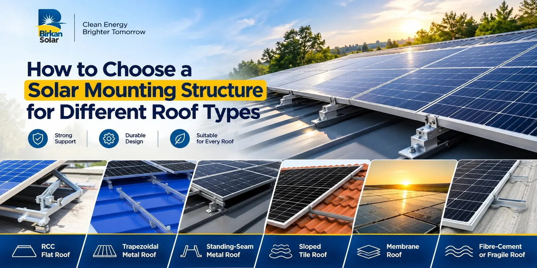
The right solar mounting structure for a roof is the system that transfers wind, dead, live and installation loads into the building without damaging waterproofing, drainage or the roof covering. Selection begins with the roof construction and condition, then considers structural capacity, attachment points, wind exposure, module layout, corrosion, cable routes, fire and maintenance access. A mounting method should never be chosen from a product photograph or a price-per-kilowatt quote alone.
Birkan Solar presents rooftop solar panel structures and broader solar installation solutions. For a project-specific proposal, buyers should provide roof drawings, an actual survey, module details, location, intended layout and the building owner’s constraints. Final design, fixing and waterproofing details should be approved by competent structural and electrical professionals.
Why Roof Type Changes the Mounting Decision
A flat reinforced-concrete terrace, a trapezoidal metal sheet, a standing-seam roof and a sloped tile roof carry and shed water differently. They also provide different structural members and safe attachment locations. The same module arrangement can therefore require a different support frame, load path, fastener, flashing detail and maintenance plan on each roof.
Roof age matters as much as roof label. Corroded purlins, cracked waterproofing, loose tiles or an undocumented concrete slab can turn an otherwise common mounting method into a high-risk choice. Survey the as-built condition rather than assuming the original construction is still intact.
Roof Type and Typical Mounting Approach
| Roof type | Typical mounting approach | Main verification |
|---|---|---|
| RCC flat roof | Ballasted or anchored raised frame | Slab capacity, waterproofing and drainage |
| Trapezoidal metal roof | Rail or mini-rail fixed to approved structural support | Sheet profile, purlins and fastener pull-out |
| Standing-seam metal roof | Compatible non-penetrating seam clamps where approved | Seam geometry and clamp certification |
| Sloped tile roof | Hooks or brackets connected to rafters or deck | Tile removal, flashing and rafter condition |
| Fibre-cement or fragile roof | Special access and independent support strategy | Fragility, structure and safe work method |
| Membrane roof | Ballasted or manufacturer-approved attachment | Membrane warranty and load distribution |
These are starting points, not automatic prescriptions. The actual solution depends on the building frame, span, local wind, array position and the roof manufacturer’s permitted details.
Start with a Measured Roof Survey
Record dimensions, slope, orientation, roof level, parapets, ridges, valleys, skylights, vents, tanks, walkways, lightning protection, drains and shaded zones. Identify the supporting structure below the visible surface. Photographs help, but dimensions and member locations must be measured and linked to a drawing.
The survey should also capture damaged sheets, ponding, leakage history, previous repairs and areas where access is unsafe. Confirm whether the roof is under warranty and which party may approve penetrations or alterations.
Confirm Structural Capacity Before Layout Freeze
The structural review should consider panel and frame weight, ballast, maintenance loads, wind uplift and downward pressure, seismic effects where applicable, snow where relevant, and load concentration at supports. For metal buildings, purlin capacity and connection behaviour may govern even when the main rafters are adequate.
Do not use a generic kilograms-per-square-metre allowance as the only check. Loads are not always uniform, and ballast blocks or rail feet can create concentrated reactions. The reviewer needs the proposed support spacing and array zones, not only total system weight.
RCC Flat Roofs
Flat concrete roofs can use ballasted frames, anchored frames or a hybrid arrangement. Ballast reduces penetrations but increases permanent weight and must resist sliding and overturning. Anchors can reduce ballast but require verified embedment, edge distance, reinforcement coordination and durable waterproofing.
Keep water paths open and avoid creating debris traps. Raised structures can improve access or use above the terrace, but they increase steel, height and wind exposure. Coordinate columns or base plates with the slab and beams instead of positioning them only for module convenience.
Trapezoidal and Corrugated Metal Roofs
On profiled metal roofs, fasteners should engage the approved structural member or follow a tested system suitable for the sheet profile and substrate. Attaching only to thin sheeting without an engineered load path can lead to leakage, deformation or uplift failure.
Check sheet thickness, coating condition, purlin spacing, existing screws and corrosion. Use compatible sealing washers and flashing details. The installation team should control fastener position and torque so seals are compressed correctly without crushing the profile.
Standing-Seam Metal Roofs
Standing-seam systems may accept clamps that grip the seam without penetration. This can protect waterproofing, but the clamp must match the exact seam shape and material. The seam-to-panel and panel-to-structure connections still need to carry the design loads.
Request compatibility evidence for the clamp and roof profile, including permitted installation torque and location. Avoid improvising with a visually similar clamp. Thermal movement of long metal sheets must remain possible after the solar rails are installed.
Sloped Tile Roofs
Tile roofs usually require hooks or brackets connected to rafters, trusses or a suitable deck beneath the tiles. Tiles are weather coverings, not structural anchors. The installer must remove and reinstate tiles without loading unsupported edges or leaving gaps.
Flashing should follow the roof construction and local weather exposure. Replacement tiles should be available before work begins. Maintain adequate clearance so rails and hooks do not press on tiles as the roof moves or workers service the array.
Fragile and Fibre-Cement Roofs
Fragile roofs demand a specific access and rescue plan. Workers should not rely on the sheet to carry body weight. A project may need crawling boards, temporary platforms, lifelines or an independent support arrangement connected to verified structural members.
The owner should assess whether roof replacement or strengthening is more practical before solar installation. Mounting a long-life array over a roof near the end of its service life can cause expensive dismantling later.
Membrane and Waterproofed Roofs
Single-ply, bituminous and other membrane roofs need a mounting detail accepted by the roof-system provider where warranty matters. Ballast mats, load spreaders and protection layers should be chemically and mechanically compatible with the membrane.
If penetrations are used, assign waterproofing responsibility clearly and inspect every completed detail before panels restrict access. Keep drains and overflow routes visible and maintain the roof manufacturer’s required inspection paths.
Wind Uplift and Array Edge Zones
Wind effects vary with building height, plan dimensions, terrain, parapets, roof slope and array location. Corners and edges can experience higher uplift than central zones. The design may require different support spacing, ballast or attachment patterns across the same roof.
Avoid copying a mounting schedule from another building. The structural calculation should use the actual site and approved loading criteria. Module clamps, rails, connectors, anchors and the roof structure must all carry the same load path.
Waterproofing and Drainage
Every attachment or ballast point should preserve drainage. Sealant alone is rarely a complete long-term detail; flashing, gaskets, compatible fasteners and workmanship controls matter. Test or inspect penetrations before the array is fully populated.
Provide enough clearance to clean drains and inspect waterproofing. Document the exact location of concealed anchors and retain photographs before they are covered. This record is valuable when future leakage is investigated.
Tilt Height and Row Spacing
Tilt influences energy yield, self-cleaning, wind load and row-to-row shading. A raised frame may improve access and reduce shading from a parapet, but it can increase structural demand. Use an energy model and structural review together rather than optimizing either in isolation.
Row spacing should preserve maintenance paths and prevent one row from shading another at the agreed design conditions. Also consider fire access, roof exits, ventilation equipment and safe distance from fragile skylights.
Material and Corrosion Compatibility
Common structures use aluminium, galvanized steel or other protected metals. Selection depends on loads, spans, environment, cost and maintenance. Dissimilar-metal interfaces may need separation or compatible fasteners to reduce galvanic corrosion.
Cut edges, drilled holes and damaged coatings require an approved repair method. Coastal salts, industrial fumes and standing water may demand stronger corrosion controls than a general urban site. Ask bidders to state material grades and protection systems rather than using the word rustproof.
Module Clamps Rails and Fasteners
Clamps must suit the module frame and permitted clamping zone. Rail spans and connector spacing should follow the structural design. Fasteners need the specified grade, coating, diameter, embedment and installation method.
Use calibrated tools where torque is specified and record sample checks. Mixing visually similar bolts or clamps during installation can invalidate the design. Label packages by roof zone to reduce errors.
Cable Management and Electrical Coordination
Plan cable routes with the structure so connectors do not rest on the roof or sit in water. Provide UV-resistant support, bend-radius control and separation from sharp edges. Keep cable trays clear of drains and maintenance paths.
Coordinate bonding, earthing and lightning protection with the electrical design. A solar frame is not automatically a complete earthing or lightning system. Record connection points and ensure roof penetrations for cables are sealed and accessible.
Maintenance and Future Roof Work
The layout should allow technicians to reach modules, clamps, drains, equipment and roof defects without walking on panels or fragile surfaces. Consider how a single module, inverter cable or roof sheet will be replaced.
If the roof may need recoating or replacement during the solar system’s life, choose modular sections and document dismantling steps. Plan temporary storage and electrical isolation for future roof work.
How to Compare Mounting Proposals
| Comparison area | What a complete proposal should state |
|---|---|
| Design basis | Roof survey, loads, wind assumptions and module data |
| Scope | Design, supply, installation, waterproofing and approvals |
| Materials | Grades, thicknesses, finishes and fastener specifications |
| Interfaces | Roof, purlin, slab, membrane and electrical responsibilities |
| QA | Incoming checks, torque, alignment and waterproofing inspection |
| Documents | Drawings, calculations, datasheets, tests and as-built records |
| Commercial basis | Quantities, exclusions, warranty and variation process |
A low price can omit structural verification, access equipment, sealing, strengthening or as-built documentation. Compare the accepted installed scope rather than kilograms of steel or the number of rails.
Common Selection Mistakes
- Selecting a mounting system before identifying the roof structure.
- Treating tiles or metal sheets as the primary load-bearing member.
- Ignoring wind edge zones and copying support spacing from another site.
- Using ballast without verifying slab capacity and sliding resistance.
- Leaving waterproofing responsibility between the solar and roofing contractors.
- Blocking drains, walkways, skylights or equipment access.
- Installing over a deteriorated roof without a lifecycle plan.
A Practical Selection Sequence
- Survey roof type, condition, dimensions, drainage and access.
- Locate the structural members and review available drawings.
- Create the energy layout with setbacks and maintenance routes.
- Calculate project-specific loads and roof reactions.
- Select and detail attachments, rails, clamps and waterproofing.
- Coordinate cables, earthing, lightning and fire access.
- Approve QA, installation and handover requirements before work.
Roof Warranty and Responsibility Matrix
Confirm who owns the existing roof warranty and who is permitted to modify it. The roofing contractor, structure supplier, solar installer and building owner may each control a different interface. Record responsibility for surveys, penetrations, flashings, sealants, leak testing, repairs and future access before installation begins.
A responsibility matrix should also define the response when a leak appears. Investigation must distinguish an old roof defect from a new penetration or blocked drain. Baseline photographs, water-test records where appropriate and signed inspection points reduce later disputes.
Temporary Works and Installation Safety
The permanent structure calculation does not replace temporary-work planning. During installation, incomplete rails and partially clamped modules may be vulnerable to wind. Define safe storage, daily securing, lifting limits and the sequence for releasing temporary restraints.
Plan fall protection, fragile-surface controls, roof access, edge protection, rescue and weather stoppage. Attachment of safety lines to the solar frame should occur only where it has been specifically designed and approved for that duty.
Quality Checks During Installation
Inspect the first completed mounting bay before repetitive work continues. Verify member sizes, support locations, anchor or clamp type, fastener engagement, torque, seal detail, rail alignment, module clamping zone and cable clearance. Use a zone-based checklist tied to drawings.
Track nonconformities and repairs. Unapproved extra holes, mixed fasteners, distorted rails or damaged coatings should be corrected through a documented method. Final inspection should include roof cleanliness because swarf, loose hardware and packaging can block drains or corrode the surface.
Handover Records for the Building Owner
Provide structural calculations, roof and array drawings, product datasheets, fastener and waterproofing details, inspection records, photographs of concealed work, warranties and maintenance instructions. Identify safe access paths and any restrictions on walking, cleaning or future alterations.
The as-built drawing should show actual attachment locations and cable penetrations. When a roof is repaired years later, this information prevents unnecessary removal and helps contractors avoid hidden anchors or live electrical routes.
Lifecycle Inspection Schedule
Schedule inspections after severe weather and at intervals appropriate to the site. Review loose or missing hardware, movement, corrosion, seal condition, roof damage, blocked drainage and cable support. Standing-seam clamps, ballast and penetrations require different checks.
Use comparable photographs and recorded observations rather than a generic maintenance signature. If one zone shows movement or leakage, assess similar details across the array. Early correction can protect both the roof and the solar investment.
Coordination with Rooftop Equipment
Solar rows must be coordinated with HVAC units, smoke vents, water tanks, antennas and future service zones. Keep equipment removal paths open and avoid placing modules where hot exhaust, shading or maintenance activity will create repeated problems. Confirm the clear working area required by each equipment supplier.
Where pipes or ducts cross the array, provide durable supports and access rather than resting services on rails. Future equipment replacement should not require unsafe module removal. Record reserved zones on the as-built roof plan.
Planning for Expansion
If the owner may add modules later, assess roof capacity, inverter and cable routes, fire access and structural grid at the initial stage. Leaving empty roof area does not guarantee that it will accept the same structure or module in future.
Document the assumptions for expansion and protect spare attachment locations or pathways. A later module model may have different dimensions and clamping zones, so the extension must receive a fresh compatibility and load review.
Frequently Asked Questions
1. Can one mounting structure work on every roof?
No. Roof profile, supporting members, loads, waterproofing and permitted attachment methods differ.
2. Is a ballasted system always penetration-free?
It can avoid structural penetrations, but membrane protection, drainage, sliding and ballast loads still require design.
3. Can solar panels be fixed directly to metal roofing sheets?
The load path and approved fixing detail must be verified; thin sheeting alone may not provide adequate resistance.
4. Are standing-seam clamps suitable for every seam?
No. Clamp geometry and installation must match the exact seam and roof-system requirements.
5. What should be checked on an RCC roof?
Review slab and beam capacity, waterproofing, drainage, anchors or ballast, parapets and access.
6. How are tiled roofs protected from leakage?
Use structurally connected hooks or brackets with compatible flashing and careful tile reinstatement.
7. Does higher tilt always improve solar output?
No. Tilt affects yield, wind, spacing and shading; the optimum is project-specific.
8. Why are roof corners important?
Edge and corner zones can experience higher wind uplift and may need different attachment or ballast.
9. Should an old roof be repaired before solar installation?
Yes when defects or remaining life could force early removal of the array.
10. What documents should the installer provide?
Keep approved drawings, calculations, material data, inspection records, waterproofing details and as-built information.
11. How much roof clearance is needed?
Clearance depends on heat, drainage, maintenance, roof geometry and structural design.
12. How can buyers request a roof-specific proposal?
Share a survey, roof drawings, module data, location and operating constraints through the company contact channel.
Match the Structure to the Roof Before Installing the Array
A dependable rooftop system begins with the building, not the catalogue. Review Birkan Solar’s project experience, About Usinformation and rooftop structure range, then use the Contact Us page to share roof drawings, photographs, location, module details and access constraints for a project-specific survey and proposal.